
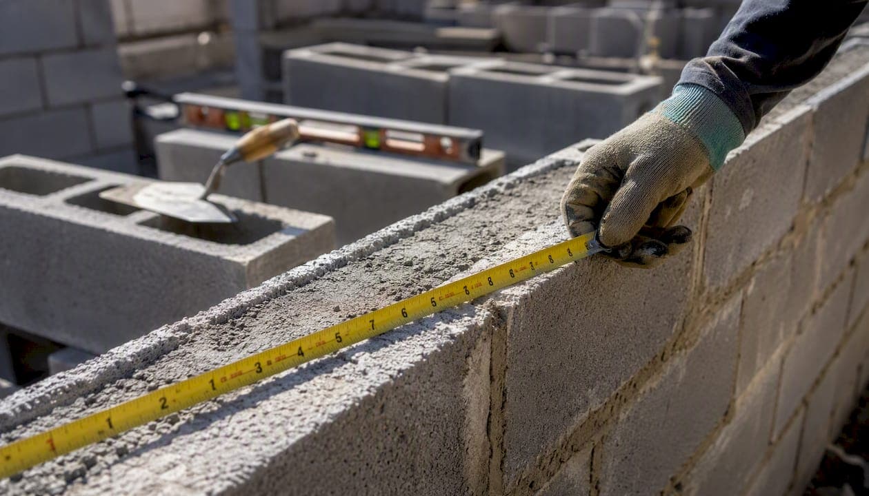
A masonry layout plan is a construction drawing and set of field instructions that shows how to place brick, concrete masonry unit (CMU), or stone: coursing, bond pattern, openings, reinforcement, and reference points. Estimators use it to take off quantities; project managers use it to sequence work and catch conflicts early; foremen use it to lay out walls and keep crews productive. A good plan follows modular coordination guidance from groups like the Concrete Masonry & Hardscapes Association (CMHA), often gets simplified into a BIM-derived shop drawing, and gets checked in the field with tools as basic as a laser level and a story pole.
Key Takeaways
A masonry layout plan works because it translates design intent into modular, buildable instructions that estimators, PMs, and foremen can act on without guessing.
| Point | Details |
|---|---|
| Check modularity first | Confirm exterior dimensions divide evenly by 8 in. before pricing or laying out a wall. |
| Simplify for the crew | Convert dense architectural sheets into lift drawings so foremen work off one clear page. |
| Watch for red flags | Missing anchors, conflicting rebar notes, and non-modular dimensions all warrant an RFI. |
| Use consistent field tools | Laser levels, story poles, and reference lines keep coursing accurate lift after lift. |
| Build the checklist into routine | Fold modular checks and lift tracking into your existing RFI and submittal workflow. |
Table of Contents
- What does a masonry layout plan include?
- How do estimators, PMs, and foremen use layout plans?
- Why does the 8-inch module matter?
- When should you build a BIM model or shop drawing?
- What tools and checks keep field layout accurate?
- What red flags should trigger an RFI?
- What should a field-ready checklist include?
- Frequently Asked Questions
- Sources
What does a masonry layout plan include?
Most layout plans pull from a common set of elements, whether they come straight off the architect's sheets or get condensed into a shop drawing for the crew. Knowing where to look saves you from flipping through forty pages of a spec book looking for one dimension.
Here's what to scan for on any set of masonry drawings:
- Wall elevations and plan views showing overall dimensions, wall lengths, and heights.
- Sections cutting through the wall to show cavity width, insulation, and ties.
- Coursing and bond pattern notes (running bond, common bond, stack bond) that dictate how units stack and overlap.
- Control joint and expansion joint locations, usually marked with a specific symbol on the elevation.
- Openings with sill and head details for windows, doors, and louvers.
- Lintel and bond beam details, including bearing length and reinforcement.
- Rebar and reinforcement schedules calling out bar size, spacing, and lap length.
- Anchor and tie locations, especially at interfaces with steel, precast, or curtain wall.
- Reference and grid lines tying the wall back to the building's structural grid.
- Dimensions and material notes specifying unit type, color, and finish.
An estimator scanning for quantities pulls CMU or brick counts from the elevations, linear feet of reinforcement from the schedule, and lintel counts from the opening callouts. Architectural and structural plans carry all of this information, but they're dense and built for design review, not for a mason on a scaffold. That's where shop drawings, sometimes called shop drawing submittals, come in: a condensed, field-focused subset of the full drawing set aimed squarely at what a crew needs to build.
How do estimators, PMs, and foremen use layout plans?
Each role reads the same drawing set differently, and the handoffs between them determine whether a job runs smooth or gets stuck waiting on answers.
Estimators mine the plan for quantities: unit counts, opening sizes, coursing height adjustments, and any non-standard details that add labor. The most common takeoff trap is missing a modular mismatch that will force cutting, which adds labor hours nobody budgeted for. Project managers use the same plan to time procurement, sequence trade coordination (steel, mechanical, electrical embeds), and flag change triggers before they become disputes. Foremen turn the plan into action: producing or using lift drawings, setting story poles, striking reference lines, and sequencing wall sections to keep crews moving without backtracking.
A workflow that keeps everyone aligned looks something like this:
- Review the full plan set for modular conflicts and missing information.
- Flag and resolve non-modular dimensions or unclear details before pricing or scheduling.
- Produce a simplified shop or lift drawing for field use.
- Coordinate pre-install with other trades on embeds, anchors, and openings.
- Execute field layout: reference lines, story poles, and course-by-course checks.
Skipping step two is the single most common reason a bid comes in low or a crew loses a half day mid-wall.
Why does the 8-inch module matter?
Concrete masonry is designed around a standard module of 8 inches (203 mm), both vertically and horizontally, according to CMHA's modular layout guidance. When a building's plan dimensions divide evenly by 8 inches, every course can be built with full or half-length units, keeping the bond pattern intact and corners clean.
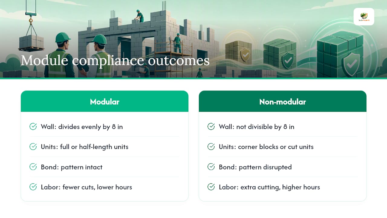
Here's the quick test: take the exterior wall dimension and divide by 8. If it comes out even, you're in good shape. If it doesn't, you're looking at either a corner block solution, a slight dimensional adjustment, or extra cutting on-site, and cutting costs real labor hours and weakens the wall's appearance and structural continuity.
Pro Tip: Run the modular check during estimating, not after the contract is signed. Catching a non-modular dimension in the bid phase gives you room to negotiate a fix; catching it in the field means eating the cost.
When should you build a BIM model or shop drawing?
BIM modeling for masonry earns its keep on jobs with complex details, contract requirements for coordination, or a genuine need for accurate takeoff data. On a simple single-story CMU box, hand-drawn shop drawings might be plenty. On a job with curtain wall interfaces, embedded steel, and tight tolerances, a model catches problems no one sees on paper.
A masonry-specific BIM model typically produces:
- Simplified 2D lift or shop drawings for crew use.
- Rebar dowel layouts and lap schedules.
- Embed and anchor location diagrams.
- Isometric views for tricky details.
- Material quantity reports for procurement.
- Scaffold and equipment planning notes.
The Pankow Foundation's BIM deliverables guide makes the case plainly: a dense architectural sheet buries the information a mason needs among dozens of details that don't apply to the wall in front of them. A crew-focused lift drawing strips that away, showing only what applies to that lift, that section, that day. The typical workflow: import CAD backgrounds, model masonry elements to the detail level the job requires, extract lift drawings, and get them to the foreman and procurement team before material shows up on site.
What tools and checks keep field layout accurate?
Converting a drawing into an actual wall depends on a short list of tools used consistently, not fancy equipment. Crews rely on laser levels for plumb and elevation checks, story poles to transfer coursing heights, chalk lines and string lines for straight runs, transits for larger layouts, and simple layout templates for openings and corners.
Best practices that keep a wall true:
- Set primary reference lines off the building's structural grid, not off an adjacent wall that might already be out of square.
- Verify corners and overall squareness before the first unit goes down.
- Transfer coursing heights with a story pole rather than measuring up from the ground each time.
- Confirm embed and anchor locations against the plan before laying units around them.
The Autodesk Construction Blog's masonry guide notes that consistent joint thickness and regular plumb and level checks matter as much for code compliance as for appearance.
Pro Tip: Condense the full plan into a one-page lift drawing or field memo before the crew starts. A foreman who has to flip through a 60-page set to find one rebar note loses time every single lift.
What red flags should trigger an RFI?
Some plan issues are minor annoyances. Others stop a wall cold. Learn to tell the difference early.
Watch for these red flags:
- Non-modular plan dimensions that force cutting or corner block substitutions.
- Missing embed or anchor information at trade interfaces.
- Conflicting rebar details between structural and architectural sheets.
- Unclear lintel or bond beam bearing and reinforcement notes.
- Omitted control joint locations.
- Unresolved conflicts with mechanical, electrical, or steel trades.
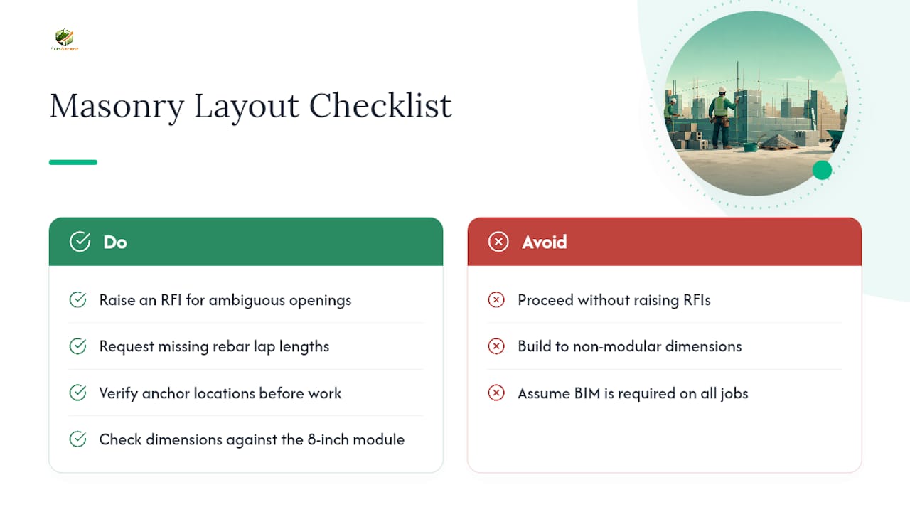
Issue an RFI immediately when you spot any of these:
- A dimension to an opening that doesn't match between elevation and plan view.
- Rebar lap lengths that aren't specified or contradict the schedule.
- Anchor or tie locations that aren't shown at a known interface point.
- A plan dimension that fails the 8-inch modular check with no noted alternative.
Ignore these and the costs show up fast: cutting eats labor hours and weakens bond patterns, unlocated anchors delay installation while everyone waits on an answer, and rebar conflicts can mean tearing out work that already passed inspection.
What should a field-ready checklist include?
A one-page checklist keeps modular checks, procurement confirmations, and field prep from falling through the cracks between the office and the job site.
- Estimator check: confirm modular dimensions, list all openings, tally reinforcement quantities, and flag any special or non-standard units.
- PM check: confirm anchor and embed details with other trades, verify procurement lead times, and lock in the sequencing plan.
- Foreman check: establish reference lines, place story poles, and distribute the current lift drawing to the crew before work starts.
A useful field sheet structure includes a project header, critical dimensions with modular pass or fail notes, a running list of RFIs created, lift numbers with sequence order, and a line for immediate contact or action items. Fold this into your existing RFI submittal process so it becomes a routine step on every job, not a special exercise you only remember after something goes wrong.
What I've learned handing crews their first set of plans
The first thing I do with a new plan set is run the modular check before anything else. If the exterior dimensions don't divide cleanly by 8 inches, I want that flagged before pricing, not discovered mid-wall. The second thing: a simple, clear lift drawing beats a beautifully detailed architectural sheet every time, because a foreman needs three numbers and a sketch, not forty pages. That's the gap Subascent's estimating and field tools are built to close for masonry subs.
Frequently Asked Questions
What is a masonry layout plan used for? It coordinates coursing, bond pattern, openings, reinforcement, and reference points so estimators can take off quantities and crews can build to design without guesswork.
How is a masonry layout plan different from a shop drawing? The layout plan is typically part of the architectural or structural set. A shop or lift drawing is a condensed, crew-focused version pulled from that plan, often generated from a BIM model, showing only what a specific lift or wall section needs.
Why does the 8-inch module matter in masonry layout? Concrete masonry units are sized around an 8-inch module. Plan dimensions divisible by 8 inches let crews build full courses without cutting units, which saves labor and keeps bond patterns intact, per CMHA guidance.
What triggers an RFI on a masonry layout plan? Ambiguous opening dimensions, missing rebar lap lengths, unlocated anchors, and plan dimensions that fail the modular check all warrant an RFI before work proceeds.
Do all masonry projects need a BIM model? No. Simple projects often work fine with traditional shop drawings. Complex interfaces, tight tolerances, or contract requirements for coordination make a BIM model worth the investment.
Sources
- TEK 05-16: Masonry Layout Planning (Concrete Masonry & Hardscapes Association)
- A Complete Guide to Masonry Construction (Autodesk Construction Blog)